1. Introduction: Why CIP System Design Matters in Commercial Breweries
In a large commercial brewery, cleaning is an essential part of production rather than a separate maintenance activity.
Brewhouse vessels, fermentation tanks, bright beer tanks, heat exchangers, and process pipelines come into contact with wort, yeast, beer, and cleaning chemicals. If cleaning procedures are inconsistent or equipment is difficult to clean, the brewery may face increased contamination risks, production interruptions, and unnecessary water and chemical consumption.
A Cleaning-in-Place (CIP) system is designed to clean process equipment and pipelines without requiring operators to dismantle the equipment for routine cleaning.
For a commercial brewery, an effective CIP system should do more than supply cleaning liquid. It must deliver the correct cleaning solution at the required temperature, concentration, flow rate, and contact time to every designated cleaning circuit.
This requires coordinated engineering between CIP tanks, pumps, valves, pipelines, spray devices, process vessels, and control systems.
A poorly designed CIP system may result in insufficient cleaning coverage, excessive chemical consumption, long cleaning cycles, or difficulty managing multiple production areas.
This article explains how to design an industrial CIP cleaning system for a large commercial brewery, from initial process planning to equipment selection, cleaning circuit configuration, automation, and future expansion.
2. Understand the Brewery Cleaning Requirements First
Before selecting CIP tanks and pumps, the brewery’s cleaning requirements should be identified.
Different equipment sections have different cleaning characteristics. A mash tun may contain grain residues, while fermentation tanks may contain yeast deposits and beer residues. Product pipelines and heat exchangers also require cleaning procedures suited to their internal geometry and operating conditions.
A CIP system should therefore be designed according to the equipment being cleaned, the type of residue, and the required cleaning procedure.
Main Brewery Equipment Requiring CIP
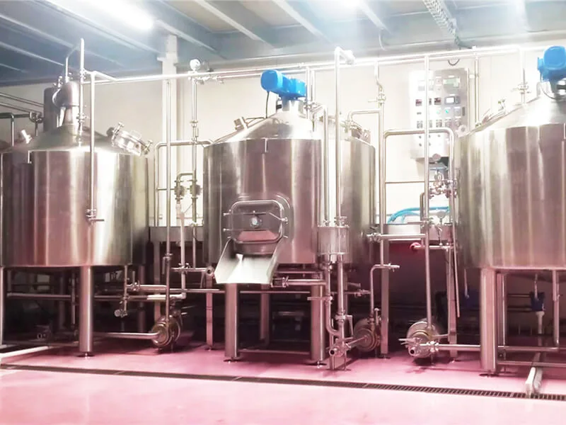
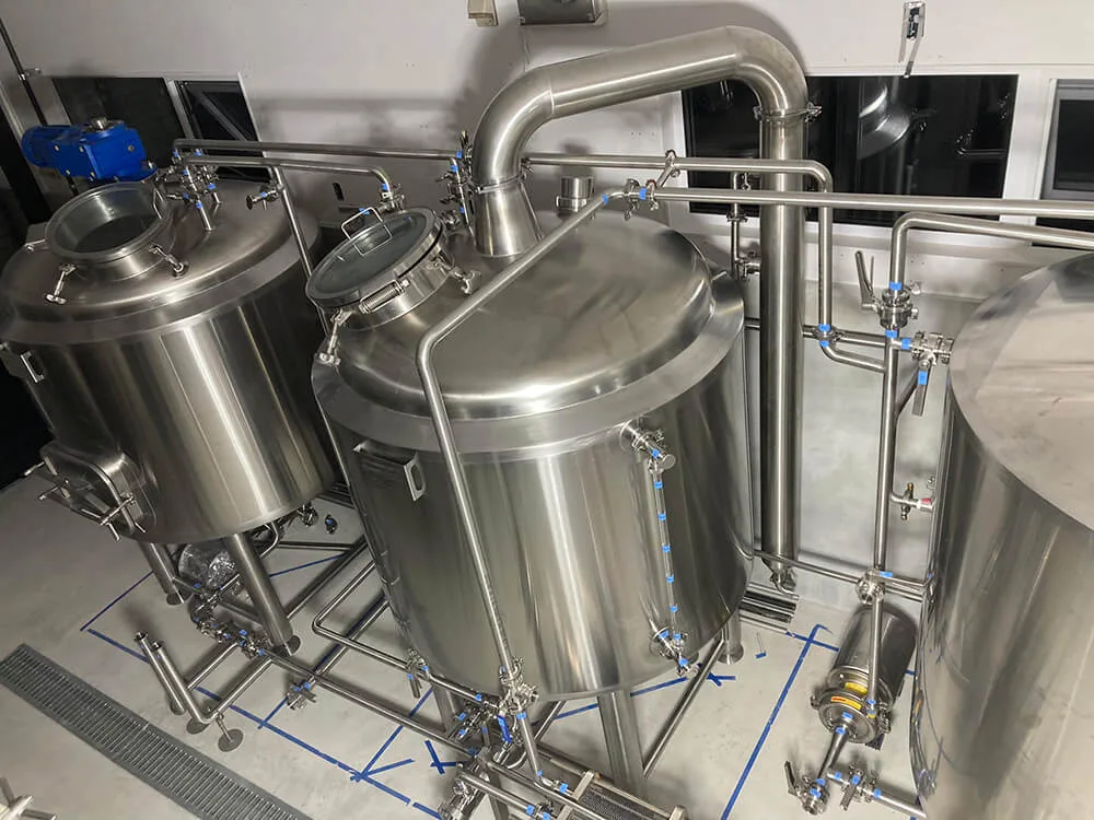
Brewhouse Vessels
Mash tuns, lauter tuns, boil kettles, and whirlpool tanks require cleaning after production according to their respective process conditions.
Cleaning requirements may differ depending on the vessel’s internal structure, spent grain handling, wort residues, and installed spray devices.
Fermentation Tanks
Fermentation tanks require cleaning after beer transfer. The procedure should address yeast residues, beer deposits, and other organic material that may remain on the tank’s internal surfaces.
Bright Beer Tanks
Bright beer tanks require suitable cleaning and sanitization procedures before receiving the next batch of finished beer.
Heat Exchangers
Plate heat exchangers require suitable CIP circulation to clean their internal product channels. The cleaning circuit must consider the heat exchanger’s design, allowable operating conditions, and chemical compatibility.
Process Pipelines
Wort, beer, yeast, and other product-contact pipelines must be included in the cleaning plan. Cleaning liquid needs to reach the relevant pipeline sections and return to the CIP station through an appropriate circuit.
Build an Equipment Cleaning Matrix
Before designing the CIP station, create a cleaning matrix that identifies which equipment requires cleaning and how it will be connected.
| Equipment | Main cleaning considerations |
|---|---|
| Mash tun | Grain residues and internal surface coverage |
| Lauter tun | Grain residues, false bottom, and drainage areas |
| Boil kettle | Wort deposits and internal surfaces |
| Whirlpool tank | Wort residues and bottom collection areas |
| Fermentation tank | Yeast deposits and tank wall coverage |
| Bright beer tank | Beer residues and hygienic preparation |
| Heat exchanger | Internal channel circulation and chemical compatibility |
| Product pipelines | Flow, drainage, and circuit isolation |
This matrix provides the foundation for determining the CIP station capacity, cleaning circuits, and operating sequence.
3. Select the Right CIP Station Configuration
The CIP station is the central part of the brewery cleaning system.
It stores cleaning solutions, supplies them to the selected equipment, and receives the return liquid for circulation or recovery according to the cleaning procedure.
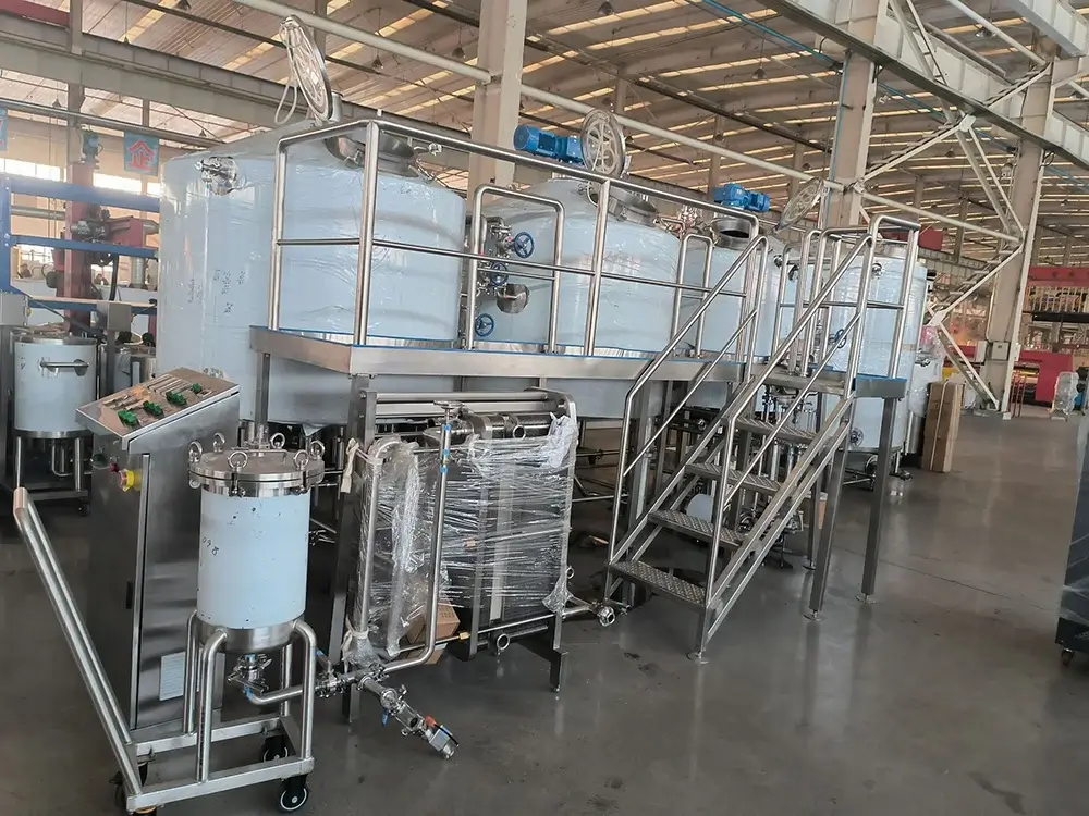
For a large commercial brewery, the station may include multiple storage tanks, circulation pumps, valves, instruments, and a control system.
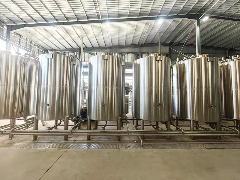
Typical CIP Tank Configuration
An industrial brewery CIP station may include:
Caustic Tank
Stores alkaline cleaning solution used to remove organic residues such as proteins, yeast deposits, and other process contaminants.
Acid Tank
Stores acid cleaning solution when required by the cleaning procedure. Acid cleaning can help remove mineral deposits and other inorganic residues.
Sanitizer Tank
Stores the selected sanitizing solution for use according to the brewery’s validated sanitization procedure.
Hot Water Tank
Provides hot water for pre-rinsing, intermediate rinsing, final rinsing, or other cleaning stages, depending on the process design.
The number and capacity of CIP tanks depend on the number of cleaning circuits, cleaning frequency, chemical recovery strategy, water consumption, and whether multiple equipment sections need to be cleaned simultaneously.
One-Tank, Two-Tank, or Multi-Tank CIP Systems?
Different brewery sizes and cleaning requirements may justify different CIP configurations.
A simple system may use fewer tanks and require more frequent solution preparation. A larger multi-tank system can provide separate storage for alkaline solution, acid solution, sanitizer, and hot water.
The advantage of a multi-tank arrangement is that different cleaning solutions can be prepared and managed separately, reducing the need for repeated tank conversion.
However, more tanks also increase the initial equipment investment, footprint, and maintenance requirements.
The correct configuration should be determined through a cleaning process assessment rather than by selecting the largest available CIP station.
4. Calculate CIP Tank Capacity and Pump Requirements
CIP equipment should be sized according to actual cleaning demand.
A common design mistake is selecting CIP tanks based only on brewery production capacity. The required CIP capacity depends more directly on the volume of each cleaning circuit, the number of cleaning operations, and the operating schedule.
How to Determine CIP Tank Capacity
The CIP tank capacity should account for:
- Internal volume of the equipment being cleaned.
- Volume of the cleaning pipeline circuit.
- Required liquid level for pump operation.
- Minimum operating volume.
- Cleaning solution recovery requirements.
- Cleaning frequency.
- Number of circuits operating simultaneously.
- Additional allowance for operational requirements.
A useful starting point is to estimate the liquid volume needed to fill the selected cleaning circuit and maintain stable circulation.
The tank must provide enough usable liquid for the cleaning operation while maintaining an appropriate operating level.
The nominal tank volume should not be treated as the same as its usable cleaning volume.
How to Select CIP Pumps
CIP pumps must provide the flow and pressure required by the cleaning circuit.
Important selection factors include:
- Required flow rate.
- Pipeline diameter and length.
- Pressure losses.
- Valve and fitting resistance.
- Spray device requirements.
- Heat exchanger pressure drop.
- Liquid temperature.
- Chemical compatibility.
- Pump material and mechanical seal selection.
For pipeline cleaning, the required flow rate should be determined according to the pipe diameter and the cleaning velocity specified by the applicable process design.
For tank cleaning, the spray device must receive the flow and pressure required by its design.
One pump configuration may not be suitable for every cleaning application. Large breweries may use different pumps or independently controlled circuits for tank cleaning and pipeline circulation.
5. Design the CIP Cleaning Circuits
Cleaning circuit design is one of the most important parts of an industrial brewery CIP system.
The purpose of a cleaning circuit is to establish a controlled path through which cleaning solution flows from the CIP station, passes through the selected equipment, and returns to the station or designated recovery point.
The circuit must be designed so that the required surfaces receive adequate cleaning action.
Separate Cleaning Circuits by Process Area
A large brewery may divide its cleaning circuits into several groups:
Brewhouse CIP Circuit
Cleans mash tuns, lauter tuns, kettles, whirlpool vessels, and associated product pipelines according to the equipment configuration.
Fermentation Area CIP Circuit
Cleans fermentation tanks, beer transfer pipelines, and associated valves and connections.
Bright Beer and Packaging CIP Circuit
Cleans bright beer tanks and applicable product pipelines leading to packaging equipment.
Heat Exchanger CIP Circuit
Provides circulation through the product channels of the heat exchanger using an approved cleaning procedure.
The exact circuit arrangement depends on the equipment layout and whether certain equipment sections can share a cleaning circuit.
Why Circuit Isolation Is Important
If several tanks are connected to a common CIP supply and return system, the design must prevent cleaning solution from flowing into equipment that is not intended to be cleaned.
Proper isolation can be achieved through a suitable combination of manual valves, automated valves, valve manifolds, and control interlocks.
A well-designed system should make it clear which tank or pipeline is being cleaned at any given time.
This helps reduce the risk of cross-contamination and makes cleaning operations easier to manage.
Avoid Dead Legs and Poor Drainage
Pipeline geometry can strongly influence CIP performance.
Long dead legs, poorly positioned valves, unnecessary branches, and low points where liquid accumulates can make cleaning and drainage more difficult.
During the design stage, engineers should consider:
- Pipeline slope and drainage.
- Valve and fitting arrangement.
- Branch connection design.
- Return pipeline routing.
- Equipment isolation.
- Accessibility for inspection and maintenance.
Good hygienic design should be incorporated into both the process equipment and its supporting pipeline system.
6. Understand the Four Key Factors of CIP Cleaning
CIP cleaning performance depends on the combined effect of time, temperature, chemical concentration, and mechanical action.
These factors are often described as the four main variables of cleaning.
Changing one factor may affect the others, but the cleaning procedure must remain suitable for the equipment, residue, and chemical system.
Cleaning Time
Cleaning solution must remain in contact with the target surfaces for sufficient time to remove the relevant residues.
The required time depends on the type of residue, cleaning chemical, temperature, flow conditions, and equipment geometry.
Cleaning Temperature
Temperature influences the cleaning performance of many alkaline and acid solutions.
However, higher temperatures are not automatically better. The maximum allowable temperature must consider chemical recommendations, equipment design limits, gasket materials, and product residue characteristics.
Chemical Concentration
The cleaning solution must maintain an appropriate concentration throughout the cleaning cycle.
Too little chemical may result in insufficient cleaning. Excessive concentration may increase chemical consumption, corrosion risks, and operating costs.
Chemical concentrations should follow the chemical supplier’s recommendations and the brewery’s validated cleaning procedure.
Mechanical Action
Mechanical action is generated by liquid flow, turbulence, spray impact, and circulation.
For pipelines, appropriate flow velocity helps improve cleaning performance.
For tanks, spray devices must provide sufficient coverage of internal surfaces.
The four factors must be evaluated together. A CIP system should not rely on high chemical concentration to compensate for inadequate flow or poor spray coverage.
7. Select the Right Tank Cleaning Devices
Tank cleaning devices determine how cleaning liquid is distributed across internal vessel surfaces.
The selection should be based on tank dimensions, internal geometry, residue characteristics, cleaning requirements, and the available CIP supply conditions.
Static Spray Balls
Static spray balls are commonly used in brewery tanks.
They distribute cleaning liquid through multiple openings and rely on the supplied flow and pressure to create spray coverage.
They are suitable for many conventional tank cleaning applications when correctly selected and installed.
Rotary Spray Devices
Rotary spray devices use the movement of the cleaning liquid to create a rotating spray pattern.
They may be suitable for applications requiring more targeted mechanical cleaning action.
Rotating Jet Heads
Rotating jet heads can provide more concentrated cleaning action and may be considered for larger vessels or more demanding residue conditions.
Their selection requires careful evaluation of flow rate, pressure, coverage, and cleaning validation requirements.
Consider Tank Geometry
A tank cleaning device must be positioned to cover the required internal surfaces.
Engineers should consider:
- Tank diameter and height.
- Tank roof and bottom geometry.
- Internal fittings and obstructions.
- Manway arrangement.
- Spray device location.
- Required cleaning flow and pressure.
- Drainage and liquid return.
The presence of a spray ball does not automatically guarantee complete cleaning. Spray coverage and cleaning effectiveness should be verified under the intended operating conditions.
8. Design the CIP Pipeline and Return System
The CIP pipeline system connects the cleaning station to the equipment being cleaned.
It must support reliable circulation, appropriate isolation, and effective drainage.
CIP Supply Pipeline
The supply pipeline transports cleaning solutions from the CIP station to the selected equipment.
Its diameter should be selected according to the required flow rate and acceptable pressure loss.
The layout should avoid unnecessary pipe lengths, excessive fittings, and difficult-to-maintain connections.
CIP Return Pipeline
The return pipeline carries used cleaning liquid back to the CIP station or designated discharge point.
It should be designed to avoid unnecessary liquid accumulation and support stable return flow.
Depending on the process, return flow may be monitored to help operators evaluate cleaning circulation.
Pipeline Material and Connection Design
CIP pipelines should use materials compatible with the cleaning chemicals, operating temperatures, and process requirements.
Stainless steel is widely used in commercial brewery process piping.
The final design should consider:
- Material grade.
- Internal surface finish.
- Weld quality.
- Drainability.
- Valve configuration.
- Gasket and seal compatibility.
- Inspection and maintenance access.
Supply and return lines should be clearly identified to reduce operating errors during cleaning and production.
9. Integrate CIP with Fermentation Tanks and Process Pipelines
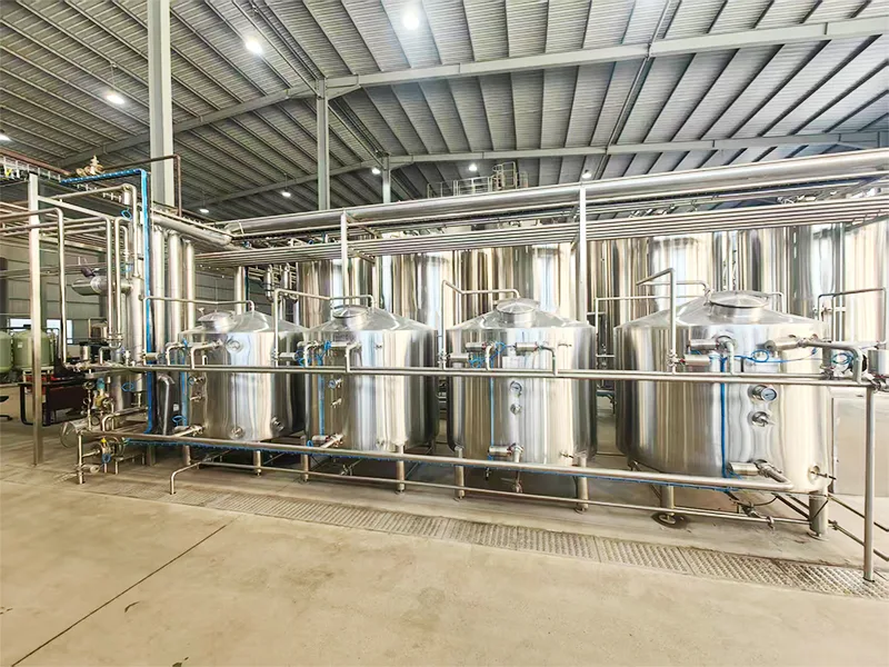
In a large brewery, the CIP system should be designed together with the fermentation area.
A fermentation tank may connect to several systems, including wort transfer, beer transfer, yeast discharge, glycol cooling, CO2, and CIP.
The arrangement of these connections influences both production operation and cleaning efficiency.
CIP Connections on Fermentation Tanks
A typical fermentation tank may include:
- CIP spray device.
- CIP supply connection.
- Beer outlet.
- Yeast discharge connection.
- Sampling valve.
- Temperature sensor.
- Pressure-related fittings and protection components appropriate to the design.
The CIP system should be able to deliver cleaning solution through the intended cleaning route and return it through a defined circuit.
Dedicated Pipeline Gallery
For larger fermentation areas, a dedicated pipeline gallery or utility corridor can simplify system management.
It can provide organized access to:
- Wort pipelines.
- Beer transfer pipelines.
- CIP supply and return lines.
- Glycol supply and return lines.
- CO2 pipelines.
- Compressed air lines.
- Drainage connections.
This arrangement can make tank isolation, cleaning, maintenance, and future expansion more convenient.
Coordinate Tank Cleaning with Production Scheduling
The CIP schedule should be coordinated with beer transfer and fermentation tank turnover.
For example, after a tank is emptied, it may enter the cleaning sequence before becoming available for the next wort transfer.
If several tanks require cleaning around the same time, the brewery should evaluate whether the CIP system can handle the required operations simultaneously or whether a sequential cleaning schedule is more appropriate.
This decision affects CIP station capacity, pump configuration, and production scheduling.
10. Apply PLC Automation to the CIP System
As brewery capacity increases, manual operation of multiple cleaning circuits can become difficult to manage.
A PLC-based CIP control system helps standardize cleaning sequences and manage the operation of pumps, valves, heating, and instrumentation.
Main Automation Functions
A commercial brewery CIP control system may include:
- CIP tank level monitoring.
- Cleaning solution temperature monitoring.
- Pump start and stop control.
- Automated valve operation.
- Cleaning circuit selection.
- Time-based sequence control.
- Temperature and concentration monitoring, where instrumented.
- Flow and return monitoring.
- Alarm management.
- Cleaning process records.
The actual functions depend on the project scope and control architecture.
Automated CIP Sequence
A typical automated cleaning sequence may include:
- Select the equipment or cleaning circuit.
- Confirm that the required valves and tank conditions are correct.
- Start the circulation pump.
- Perform the pre-rinse.
- Circulate alkaline cleaning solution.
- Perform intermediate rinsing.
- Carry out acid cleaning when required.
- Perform final rinsing.
- Apply the approved sanitization procedure.
- Complete the cycle and record the cleaning status.
Not every brewery uses the same sequence. Chemical selection, cleaning stages, recovery practices, and rinsing requirements should be established according to the equipment and cleaning validation procedure.
Improve Cleaning Traceability
For larger breweries, recording cleaning parameters can help operators review whether the intended procedure was completed.
Depending on the automation system, records may include:
- Cleaning circuit.
- Start and end time.
- Temperature profile.
- Flow conditions.
- Chemical concentration readings.
- Alarm events.
- Operator confirmation.
This information can support production management and quality-control procedures.
11. Optimize Water, Chemical, and Energy Consumption
CIP cleaning is essential, but it also consumes water, chemicals, and thermal energy.
A properly engineered system can improve resource utilization without compromising cleaning effectiveness.
Recover and Reuse Suitable Cleaning Solutions
Where chemical compatibility and cleaning procedures permit, cleaning solutions may be collected and reused for subsequent cleaning operations.
For example, alkaline or acid solutions may be returned to dedicated storage tanks for reuse after their concentration and condition are checked.
The reuse procedure should include suitable monitoring and replacement criteria.
Cleaning solutions should not be reused indefinitely without evaluating their concentration, contamination level, and cleaning performance.
Optimize Rinsing Procedures
Rinsing water consumption can be influenced by the cleaning circuit design, spray coverage, pipeline volume, and control sequence.
Appropriate flow monitoring and defined rinsing endpoints can help avoid unnecessary rinsing.
Where suitable, rinse water may be collected for lower-risk preliminary rinsing applications, subject to the brewery’s water quality and hygiene requirements.
Reduce Heat Loss
Hot cleaning solutions and water require thermal energy.
Insulating hot water tanks and suitable CIP pipelines helps reduce heat loss during storage and circulation.
The CIP system can also be coordinated with the brewery’s heat recovery system to evaluate whether recovered hot water can support cleaning operations.
However, recovered water must meet the required temperature and process conditions. Additional heating may be needed.
12. Plan CIP Capacity for Future Brewery Expansion
A commercial brewery may increase production capacity as market demand grows.
The CIP system should therefore be evaluated not only for the initial equipment installation but also for possible future expansion.
Consider Future Cleaning Circuits
When planning the initial system, consider whether additional fermentation tanks, bright beer tanks, or process lines may be installed later.
Future expansion may require:
- Additional CIP supply and return connections.
- More storage capacity.
- Higher pump flow.
- Additional valve groups.
- Expanded control functions.
- Increased hot water capacity.
- Additional drainage capacity.
Balance Initial Investment and Expansion Flexibility
Oversizing every CIP component can increase initial investment without providing meaningful benefits.
On the other hand, a system designed with no allowance for future connections may require major modifications later.
A practical design should identify which components need to be sized for future demand and which can be expanded modularly.
13. Common Mistakes in Large Brewery CIP System Design
Even a well-equipped brewery can experience cleaning problems if the CIP system is not properly integrated.
The following mistakes should be avoided.
1. Selecting CIP tanks based only on brewery batch capacity.
CIP tank capacity should be based on cleaning circuit volume, operating sequence, and cleaning demand.
2. Ignoring the cleaning requirements of individual equipment.
A fermentation tank, heat exchanger, and lauter tun may require different cleaning approaches.
3. Using the same cleaning circuit for incompatible operations.
Poor circuit separation can create cross-flow risks and complicate cleaning control.
4. Underestimating pump requirements.
Insufficient flow or pressure may affect pipeline circulation and tank spray coverage.
5. Ignoring dead legs and drainage.
Poor pipeline design can leave residual liquid and make cleaning less effective.
6. Assuming that automated cleaning is automatically effective.
Automation can control the cleaning sequence, but it cannot compensate for poor equipment design, unsuitable spray devices, or insufficient flow.
7. Overlooking chemical compatibility.
Cleaning chemicals, temperatures, seals, gaskets, and stainless steel surfaces must be compatible with the selected cleaning procedure.
8. Failing to verify cleaning performance.
The cleaning process should be checked using suitable inspection and validation methods based on the brewery’s quality requirements.
14. METO Industrial Brewery CIP System Solutions
METO is a brewery and distillery equipment manufacturer integrating engineering design, research and development, manufacturing, sales, installation, commissioning, and after-sales support.
For commercial and industrial brewery projects, METO can coordinate CIP stations with brewhouse vessels, fermentation tanks, process pipelines, glycol cooling systems, and PLC automation.
15. Conclusion: Design CIP as Part of the Complete Brewery System
An industrial brewery CIP system should not be designed as an independent cleaning station.
Its performance depends on the coordination of cleaning tanks, pumps, spray devices, process pipelines, valves, instrumentation, automation, and equipment geometry.
A well-designed CIP system can support consistent cleaning procedures, improve tank turnover, simplify operation, and help manage water, chemical, and energy consumption.
For large commercial breweries, CIP planning should begin during the overall process design stage. This allows the cleaning system to be integrated with the brewhouse, fermentation area, refrigeration system, and future production expansion.
Contact METO to discuss your brewery CIP system requirements. Share your brewhouse capacity, number of fermentation tanks, equipment layout, cleaning procedures, and automation expectations. METO’s engineering team can help evaluate a suitable CIP configuration for your brewery project.